Bollards
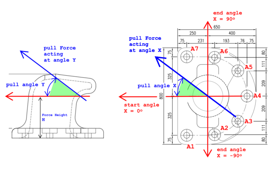
This is an informative sample calculation which shows load bearing capacities of individual steel anchors set into concrete, which attach the bollard to the quay, when bollard is subjected to mooring loads of variable intensity. The effects are calculated for an array of mooring load directions, expressed in 15 degree intervals, from 0 to 90 degrees in horizontal plane and from -15 to 45 degrees in vertical plane. Safety Factors on combined load effects of Shear, Pull Out and localised Bending on Anchors are indicated. Figures in red can be changed to suit individual appraisal.
Start by defining the bollard base shape. This is done by entering the overall width and height of the bollard. Then define the left corner radius and right corner radius. Then, enter positions of individual anchors using X-Y coordinates, referred to bottom left corner of the coordinate system which is 0,0. Then add the mooring load and height of mooring rope action.
⚓ Bollard Appraisal anchor stress · FOS
| Anchor | x (mm) | y (mm) | OTM pullout (MPa) |
Shear (MPa) |
Bend (MPa) |
Total (MPa) |
FOS (fy/Total) |
|---|